

HRT-711
Modbus TCP to HART Gateway - acts as a HART protocol Master that allows Modbus/TCP master devices to access data from HART slave devices. Replacement unit for I-87H17W.
References & Support

Features
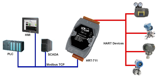 The HRT-711 Modbus TCP to HART Gateway is specially designed for the master device of HART protocol. It allows the Modbus/TCP master device to access the HART slave devices. These HART devices may be a transmitter, an actuator, a current output device and so forth. In addition, we also provide the utility software for users to configure the HRT-711. By using this module, users can integrate their HART devices into Modbus network easily.
- Support HART Short/Long frame
- Support HART Burst mode
- Allow two HART Masters
- Support Modbus/TCP Format
- Support Modbus Slave / HART Master Mode
- Support Firmware Update via Com Port
- Support On-line Replacement of HART Devices
- Support Acquire Long Frame Address Automatically
- Provide LED indicators
- Built-in Watchdog
- 4KV ESD Protection
The HART (Highway Addressable Remote Transducer) protocol uses the Bell 202 Frequency Shift Keying (FSK) standard to superimpose digital communication signals on the 4-20 mA loop current shown as below figure. HART communicates at 1200 bps without interrupting and interference with the 4-20mA signal and allows a host application (master) to send/receive digital information from a smart field device. The 4-20mA signal communicates the primary measured value - the fastest and most reliable industry standard. The digital signal can be used for additional device information including device status, diagnostics, additional measured or calculated values, etc. Therefore, the HART communication including analog and digital information provides a low-cost and very robust complete field communication solution that is easy to use and configure. HART is a master/slave protocol which provides for up to two masters (primary and secondary) and the secondary master such as handheld can be used to monitor/control the informatoin of HART bus. HART can be used in various modes such as point-to-point or multi-drop for communicating information to/from smart field instruments and central control or monitoring systems. The following are the description of two main HART operation modes.
- Relatively easy to understand and use, the HART protocol provides access to the wealth of additional information (variables, diagnostics, calibration, etc.)
- HART is a no risk solution for enhanced field communication
- Compatibility with standard 4-20mA wiring
- Simultaneous transmission of digital data
- Risk reduction through a highly accurate and robust protocol
- Increase Plant Availability
- Reduce Maintenance Costs
- Improve regulatory compliance
Utitlity
- Provide the system and communication configuration of HRT-711
- Provide the Modbus address table for HART command data
- Provide the diagnostic information of HRT-711 module and HART device
- Provide send / receive HART command to access HART device
- Provide "Load/Save" module configuration file to apply to other HRT-711 quickly
Modbus Support
| Code | name | Description |
| 01 | Read Coil Status | Read the ON/OFF status of discrete outputs in the slave |
| 02 | Read Input Status | Read the ON/OFF status of discrete inputs in the slave |
| 03 | Read Holding Registers | Read the binary contents of holding registers in the slave |
| 04 | Read Input Registers | Read the binary contents of input registers in the slave |
| 05 | Force Single Coil | Write a single output in either ON or OFF in the slave |
| 06 | Preset Single Register | Write an integer value into a single register in teh slave |
| 15 | Force Multi. Coils | Write each coil in teh sequence of coils to either ON or OFF in the slave |
| 16 | Preset Multi. Registers | Write a block of contiguous registers in the slave |
Specifications
| Ethernet Interface | |
| Controller | 10/100Base-TX Ethernet Controller (Auto-negotiating, Auto_MDIX) |
| Connector | RJ-45 x 1 (LED) |
| UART Interface (For Configuration | |
| COM Port | RS-232 (3 wires) |
| Connector | 3-pin screwed terminal block |
| HART Interface | |
| HART Channel | 1 |
| HART Interface | 2-pin screwed terminal block |
| HART Device | 2-wired or 4-wired HART devices |
| HART Topology | Point to Point or Multi-Drop |
| HART Data | Only Digital Data |
| HART Frame Type | Short and Long Frame |
| Burst Mode | Supported |
| Max. HART Device | 15 |
| Loop Resistor | 250 Ω resistor by Jumper |
| Isolation | UL1577 Spec. |
| Power | |
| Power Supply | Unregulated +10 ~ +30 VDC |
| Protection | Power reverse polarity protection, Over-voltage brown-out protection |
| Power Consumption | 1 W |
| Mechanism | |
| Installation | DIN-Rail or Wall Mounting |
| Dimensions | 72 mm x 35 mm x 121 mm (W x L x H) Detail |
| Environment | |
| Operating Temperature | -25 ℃ ~ +75 ℃ |
| Storage Temperature | -30 ℃ ~ +85 ℃ |
| Humidity | 5% ~ 95% RH, non-condensing |
References and Support
Customer Reviews (1)


...
$819.00 Each
Quantity added:

